Technical Guide
Installation, commissioning, specifications, maintenance, and troubleshooting - everything your fabricator or installer needs to set up VOLTA with confidence.
Installation
Watch: VOLTA Installation Overview
Short overview to complement the step-by-step below. Always follow the written instructions on this page and in the manuals for your specific profile and handing.
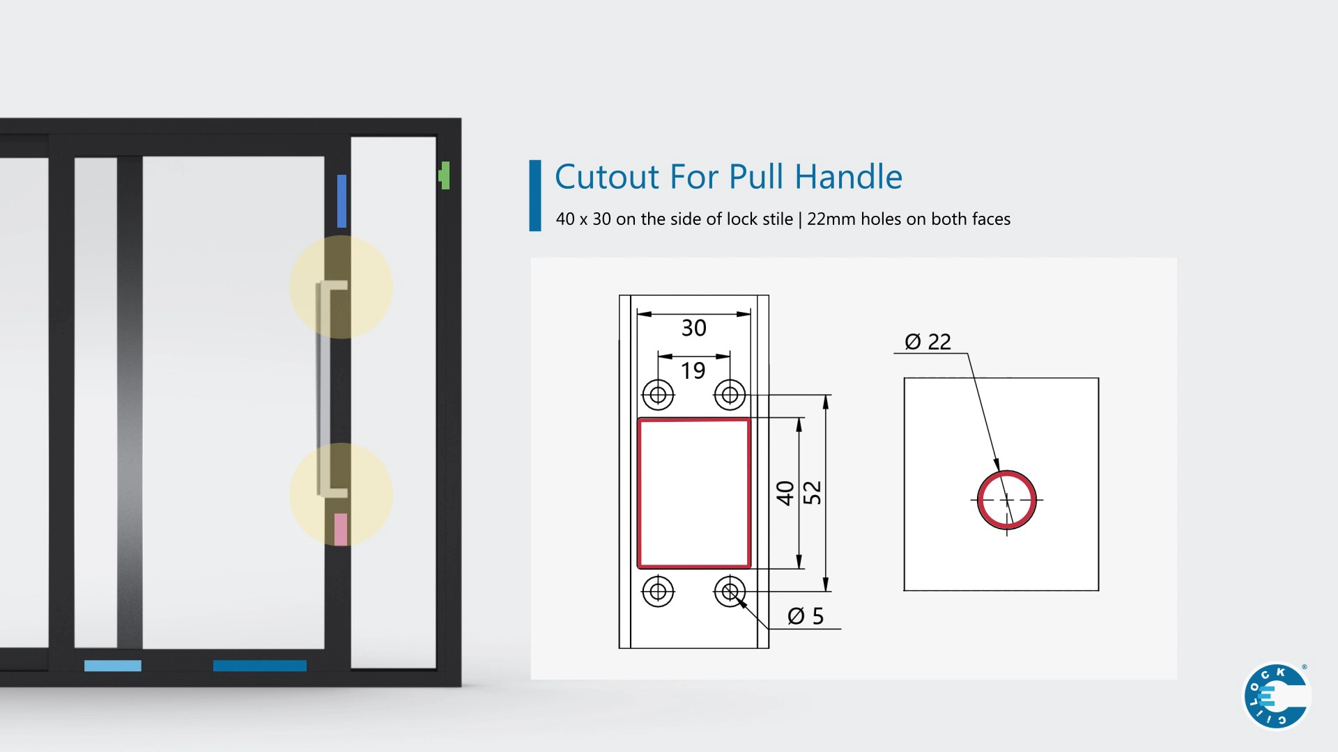
Prepare Cut-Outs
- Route the rail to match VOLTA outer dimensions. Keep slot width 33.5–34.0 mm for correct foam compression. Set roller at minimum height for reference.
- Drill stile holes as per drawing (battery, control box, roller connector, handle adaptor). See Extrusion cut-out requirement sheet (battery cut-out ~31 mm; control box ~31 mm).
- Note: Control box is installed last. Prepare the opening now, do not fix the unit.
Fit the Powered Roller
- Orient roller with height adjustment screw facing the stile. Feed both connectors at corner junction of bottom rail and stile.
- Position cables to avoid crushing. Use guides or adhere to shoulders as required.
- Set roller height to minimum before hanging the door. Adjust later.
Install the Battery Set
- Connect via Molex (red-black to battery). Orient with charging port above the battery. Fix with 2 × 6g screws.
- Drop the cable down and pull it out through the control-box opening.
Fit Handle Adaptor & Handle
- Remove handle housing. Orient with cable at the bottom. Pass connector through cut-out size. Fix base with 3 × 6g screws.
- Prepare the button (do not clip on shroud yet). Pass connector through cut-out size. Fix base with supplied screws.
Mount the Control Box
- Switch OFF (lever left). Orient with power switch above LED. Plug in roller, battery, and handle/button to labelled sockets.
- Use the two female handle ports to correct handing. Swap if directions are reversed. For the button, rotate 180° if needed. Clip on shroud and fix box with 2 × 6g screws.
Install the Charging Base
- Flip connector cap. Mount with connector pointing down. Align with the door charging port (±4 mm adjustment across 8 mm total).
For cut-out positions (battery, control box, handle adaptors, roller connector) reference the detailed drawing set and sheets.
Commissioning
- Close the door into the jamb to establish charging contact, then switch the control box ON.
- Check LED battery status (see table). Test handle and button in both directions. Correct handing if required.
- Set speed using the dial above the LED. Changes take effect after power-on. Start mid-range and adjust for panel mass and friction.
Reset after power returns: if mains power drops, toggle the control unit OFF then ON when restored.
Charging Behaviour
- Battery charges automatically when the door is fully closed onto the charging base.
- A full charge supports about 150 open/close cycles (usage dependent).
- Keep the door closed when not in use. If left open and uncharged for ~30 hours, voltage may fall below operating level.
Specifications
Electrical & system
| Classification | Extra-low voltage system ~18 V DC; low shock risk; fully concealed within extrusion. |
|---|---|
| Power supply (mains) | Input AC 100–240 V, 50/60 Hz 0.5 A; output DC 16.8 V 1.0 A (16.8 W). |
| Battery pack | 14.8 V / 3000 mAh Li-ion; replaceable. |
| Working / charging | Working 15–16.8 V DC; charging 18–24 V DC (0.5–1.0 A). |
| Ingress around floor | Components within 150 mm of finished floor sealed for full submersion; other in-frame components resist incidental water exposure. |
Performance
| Operation force | < 20 N to initiate. |
|---|---|
| Noise | < 60 dB typical. |
| Roller height adjustment | Up to 12 mm. |
| Load reference | Historic manual lists 200 kg/panel per VOLTA. Check current data for configuration. |
| Fail-safe | Manual operation available if power or roller fails. |
For precise ratings by system and profile, refer to the current VOLTA datasheet and test results.
LED Codes (power-on battery indication)
| LED Pattern | Meaning |
|---|---|
| 2 × green flash | Battery full / Maximum |
| 1 × green flash | High / ~70%+ |
| 1 × red flash | Medium / Charge soon |
| 2 × red flash or persistent red | Low / Charge required |
If mains power was interrupted, toggle the control unit OFF then ON to clear safety mode before testing.
Speed Adjustment
Use the dial above the LED to set door speed. Heavier panels tolerate higher speeds; lighter panels are best mid-range. New settings apply after the next power-on.
Maintenance
- Keep tracks clean and dry. Cover during building works. Vacuum or use a soft brush. Wipe off hose water with a damp cloth.
- Do not use corrosive liquids, scrapers, or lubricants on the rail; they damage finishes and attract debris.
- If unsure, consult your fabricator or installer. User maintenance is minimal by design.
Battery Care
- Recharge by keeping the door closed when not in use.
- Batteries are consumables; capacity declines over time. Do not self-replace—contact the supplier for service.
Troubleshooting
VOLTA Not Operating
- Check control box switch is ON. If tripped by surge/blackout, switch OFF then ON to reset.
- Battery model: close door for 30 min to charge. Confirm battery lead is connected to control unit.
- If handle not operating, check clearances and connector.
- Powered rail: ensure brush contacts rail and is plugged into control unit.
VOLTA Operates But Door Doesn’t Move
- Confirm door is unlocked. Check both rollers run in the same direction and are plugged in.
- For wheel slippage: raise roller height under load, re-seat panel, match track radius to spec, clean track (no oils/fluids).
Handle Functional Issues
- Ensure foam pad is fitted. Clearance should be neither tight nor excessive. Bed-in pivot adaptor, then re-tighten screws lightly.
- If handle pivots but no drive, verify handle adaptor is connected to control unit.
For detailed stepwise workflows (battery not charging, handle not operating, powered rail checks, wheel slippage), see the interactive guide.
Downloads
VOLTA User Operation Manual
Overview for end users: system configuration, maintenance, and quick troubleshooting.
Download PDFInstallation Instruction (AU)
Complete installation steps, wiring, LED codes, charging base details, and dimensioned drawings.
Download PDFExtrusion Cut-Out Requirements
Installer sheet with cut-outs for handle adaptors, battery, control box, and roller connector.
Download PDFHow to use VOLTA (Operating Guide)
Quick visual guide for operating via handle, remote, and switching on/off.
Open Installation Guide